Difference between revisions of "Inputprint"
m (→Weichenstrasse) |
m |
||
| Line 1: | Line 1: | ||
[[File:S_Vorsatz_Anschluss_EN.png|right|400px]] | [[File:S_Vorsatz_Anschluss_EN.png|right|400px]] | ||
| − | == | + | ==Print this site[[File:Adobe_PDF_file_icon.png|link=http://www.modellautobahnen.de/pdf/Schaltervorsatz_EN.pdf]]== |
<br> | <br> | ||
==Switchboard for Servo- und traffic light decoder== | ==Switchboard for Servo- und traffic light decoder== | ||
| Line 22: | Line 22: | ||
<br> | <br> | ||
<br> | <br> | ||
| − | |||
<br><br> | <br><br> | ||
<br><br> | <br><br> | ||
| Line 29: | Line 28: | ||
==Anschluss== | ==Anschluss== | ||
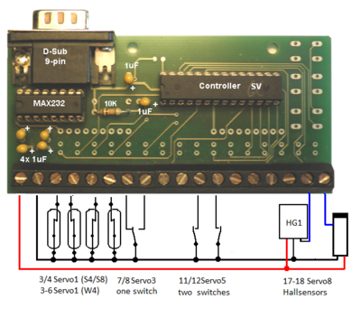
===Controlled Servodecoders S4 and S8=== | ===Controlled Servodecoders S4 and S8=== | ||
| − | [[File:S_Vorsatz_Bestueckung_neu.png| | + | [[File:S_Vorsatz_Bestueckung_neu.png|400px]]<br> |
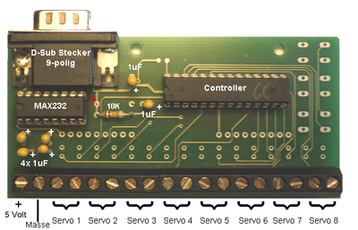
===Controlled Servodecoder W4=== | ===Controlled Servodecoder W4=== | ||
| − | [[File:S_Vorsatz_W4.png| | + | [[File:S_Vorsatz_W4.png|400px]]<br> |
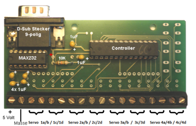
===Controlled Ampeldecoder=== | ===Controlled Ampeldecoder=== | ||
| − | [[File:Schaltervorsatz_Ampel.png| | + | [[File:Schaltervorsatz_Ampel.png|400px]]<br> |
<table Border="1"> | <table Border="1"> | ||
<tr> | <tr> | ||
| Line 47: | Line 46: | ||
</tr> | </tr> | ||
</table> | </table> | ||
| − | + | <br><br><br><br><br> | |
| − | == | + | ==Kit manual== |
siehe [[Kit contruction inputprint]] | siehe [[Kit contruction inputprint]] | ||
[[Servodecoder]] [[Trafficlightdecoder]]<br> | [[Servodecoder]] [[Trafficlightdecoder]]<br> | ||
Revision as of 22:51, 27 October 2017
Contents
Print this site
Switchboard for Servo- und traffic light decoder
The servo decoder from DC-Car (MoBa-Claus) can also be operated with a PC via the RS232 port.
Besides the progamm for the servo decoder, the CD also includes a program for operating the servos by mouse or keyboard.
With self-written programs it is feasible to implement some time-automatic sequences.
As another option for connecting to this interface is the so called switchboard.
The Prozessor get the signals from switch, reedswitch, Hallsensors or IR-Sensoren from (MINUS) and take it over RS232-chip to the connetion from the Servodecoder.
The positions off the servos are controlled with the programmer over the PC.
Anschluss
Controlled Servodecoders S4 and S8
Controlled Servodecoder W4
Controlled Ampeldecoder
| 1 | 2 | 3-10 | 11+12 | 13 | 14 | 15 | 16 | 17 | 18 |
| + 5 V Out | - Ground | Trafficlight A - D | Call Light | Night | Nothalt | Start B | Start A | auto, off | auto. off |
| green red |
Kit manual
siehe Kit contruction inputprint
Servodecoder Trafficlightdecoder
Ation
Hallsensors and R-Sensoren need a +5V connetion.
The left connector is 5V
use the servodecoder: with Extanionsconnector
| S8DCC/MOT ab 02.01.09 | W4DCC/MOT ab 26.04.09 | |
| S4DCC/MOT ab 21.10.08 | Ampeldecoder ab 10.10 |
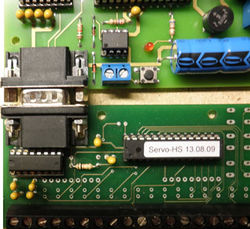
One screw is removed from the plug and the socket.<br
Then the assemblies can be plugged together and the ground connection is still given
If the switch is installed in a switchboard for the pushbuttons, a standard RS232 extension cable can be used
many servos with one switch
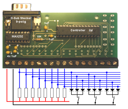
One switch can be used to operate several points simultaneously
The resistances should be 4.7 K and the diodes should be 1N4148
A control unit can be equipped with an RS232 cable (9-pin sub-D extension)
remote from the servo decoder.
