XT-Modul-Accutest
Contents
Basics DC-Car-XT
Default: Evaluation of the battery test
- Sorting out vehicles with an empty battery to reach a charging station in conjunction with a software is fully automatic charging possible)
Other options: see XT Modul
Infrared transmit and receive
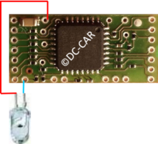
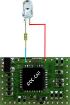
The sensor requires a phototransistor.
It can be installed:
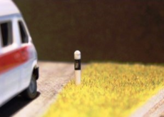
- In the guidepost
- In the street as manhole cover
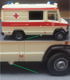
- As a sensor in a stationary vehicle
- hiding in trees, shrubs, buildings
Values for the car decoder
CV25 = 1 Transmitting from the back (infrared LEDs of the rear distance control)
or CV25 = 4 Side or bottom transmitter
CV26 Function of the vehicle with battery empty
CV27 = 2 or 10 battery test turned on
CV28 = 50 (1.2V) or 100 (2.4V) or 130 (3.6V battery)
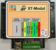
DC-Car-XT-Modul
- Switching a 3-way servo turn out
- Switching a contact to ground / GND
- Transmitting a freely selectable DC Car Infrared command
You can choose whether the respective function is resetted after a certain time or by triggering a reed contact.
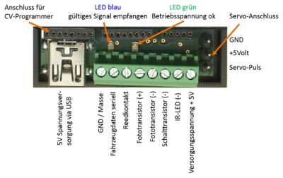
Pin assignment
Connection Description
DC voltage of 5V / 500mA via screw terminal block or the mini USB port.
- LED indicator
Green LED: 5V operating voltage available. Blue LED: received valid signal.
- Phototransistor (+ and -)
Note: Reverse marked as an LED.
- Servo connection
For direct control of a servo on the XT module.
Please pay attention to the correct connection sequence, as these might vary with the different manufacturers.
Setting XT module
...
