Vehicle number detection

Vehicle number selection
Common
In order to process a vehicle number (not the DCC address) of vehicles differently, feedback is required.
In the model railway software, this is linked to the entry of the vehicle with the DCC address.
If DC cars are not controlled via the PC, another path must be taken.
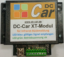
XT-module
The XT-module reacts in a signal from the vehicle.
Up to 8 numbers can be evaluated in one module.
To do this, enter the desired numbers at the top of the row.
In the vehicle the number is entered in the CV113.
The default value is 0.
With the basic settings of the XT module,
the desired functions can be set.
PC-Steuerung

With a PC control, a vehicle address is also assigned to a number.
Therefore, the PC knows whether a vehicle is allowed to use a certain lane or trigger a functions.
With the XT module additional feedback can be given to the system.
On the one hand, a recognized vehicle can trigger the transistor and thus' a feedback contact.
On the other hand, '5 bits' number from the feedback plug can be tapped and so combinations themselves with the 5 contacts are compiled
For example, only if all 5 bits (1, 2, 4, 8, 16) are active, vehicle 31 is displayed
Other bits or combinations represent another number.
For negative signals (pulses) to appear at the socket, a servo position or the switching transistor must be set to 1.
So you can freely dispose of 31 numbers.
Image right:
Position1 (CV111) Number 2 Below (CV142) No.2 Actuates the servo switches the transistor.
Position2 (CV112) Number 5 below (CV145) No. 5 Actuates the servo switches a function.
Red vehicles number 2, blue vehicle number 3 or
Lines buses 5 and trams 5 but coaches 6
sample file to download and under C: \ DC-Car_CV \ Programmer580 \ CV_Listen store
Vehicle number 1-8 (set CV113 in the vehicle) is reported to the socket. The bits are given to the first 5 pin.
| BIT 1 | 1 + 2 = 3 | |
| BIT 2 | 1 + 4 = 5 | |
| BIT 4 | 2 + 4 = 6 | |
| BIT 8 | 1 + 2 + 4 = 7 | |
| BIT 16 |
With each reading, the switching transistor or a servo position must also be actuated. (Even if not connected.)
The BITS can be connected to 5 feedback inputs of a feedback module.
If such a BIT or BIT sequence is installed in a route, the trip leads to the blocking of this route.
Since pulses should come out at the socket, you should set momentary contact (as with the reed switch) in the software.
So you have to acknowledge the wrong trip by deleting
or this feedback is also used to switch a "detour" to get the vehicle back on track.