Priorty regulation
Instructions
Foreword
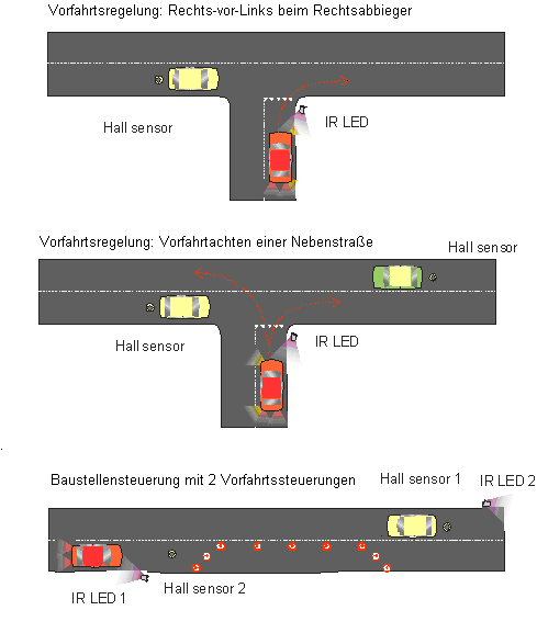
With this priority circuit, a large number of traffic situations can be simulated.
This arrangement includes a circuit which sends a DC-Car stop command for an adjustable time. The input of the circuit needs a pulse to start the stop command. Hall sensors can be installed in the roadway. This Hall sensor is triggered by the steering magnet of the vehicles.
Likewise, good reed switches are possible. The IR design also allows the use of photo transistors FTR. e.g. delineator posts)
The circuit works with a pulse extension. That is, the ON time of the stop command is extended when new pulses come from the next vehicle.
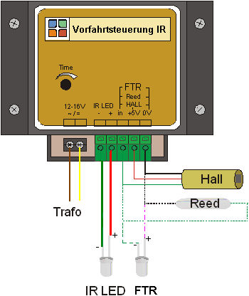
The circuit has a built-in protective resistor for the supplied infrared LED
(long connection +). This allows a maximum of 2 IR-LEDs in parallel.
To reduce the range, another resistor may be interposed.
Instructions
To supply the circuit is a model railway transformer or a DC power supply from 12 to 18 volts needed.
Several Hall sensors can be connected to the input. As can be seen from the drawing, a +5 volt power supply is provided to the Hall sensors. Red = +, black = ground, green = input supplied by the device. As a switching element, pushbuttons or reed switches can also be used, between 0V and IN
'Note:' The fototransistor FTR + (long pin) must be connected to Minus / Ground and Minus (the short pin) to Input.
With a screwdriver the time is adjustable (1 s -. 20 sec).
Examples

More information or parts: Tiny#Vorfahrt-Tiny_VT
