Difference between revisions of "Priorityrules"
m |
m |
||
| Line 2: | Line 2: | ||
<br> | <br> | ||
==priority circuit== | ==priority circuit== | ||
| + | |||
With this priority circuit , a large number of traffic situations are simulated.<br> | With this priority circuit , a large number of traffic situations are simulated.<br> | ||
This arrangement includes a circuit for a set time for DC - Car - Stop command sends . The input of the circuit needs a boost to the stop command to start . You can install the supplied Hallsensor in the road . The Hallsensor is activated by the magnet of the driving vehicles.<br> | This arrangement includes a circuit for a set time for DC - Car - Stop command sends . The input of the circuit needs a boost to the stop command to start . You can install the supplied Hallsensor in the road . The Hallsensor is activated by the magnet of the driving vehicles.<br> | ||
| Line 13: | Line 14: | ||
<br> | <br> | ||
<br> | <br> | ||
| + | |||
===Instructions=== | ===Instructions=== | ||
For the supply of the circuit is a model railway transformer or a DC 12-18 volts necessary.<br> | For the supply of the circuit is a model railway transformer or a DC 12-18 volts necessary.<br> | ||
| Line 23: | Line 25: | ||
<br> | <br> | ||
<br> | <br> | ||
| + | |||
===Examples=== | ===Examples=== | ||
[[file:vorfahrtsregelung.png]]<br> | [[file:vorfahrtsregelung.png]]<br> | ||
Revision as of 16:53, 24 February 2014
priority circuit
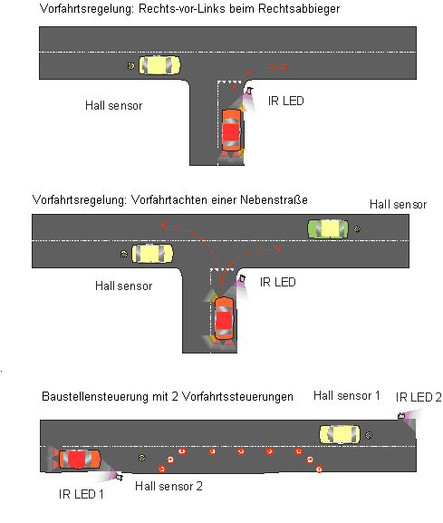
With this priority circuit , a large number of traffic situations are simulated.
This arrangement includes a circuit for a set time for DC - Car - Stop command sends . The input of the circuit needs a boost to the stop command to start . You can install the supplied Hallsensor in the road . The Hallsensor is activated by the magnet of the driving vehicles.
The circuit operates with a pulse stretching . This means that the ON- time of the stop command will be extended if new ideas come from the nearest vehicles.
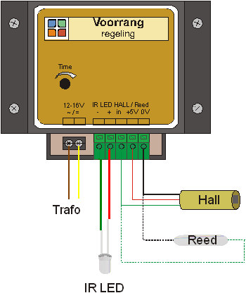
The circuit has a protection resistor for the supplied IR LED
(long connection +). This maximum 2 IR LED are possible in parallel.
To decrease the range, a further resistor may be connected in between.
Instructions
For the supply of the circuit is a model railway transformer or a DC 12-18 volts necessary.
A plurality of Hall sensors can be connected at the input. As is apparent from the drawing, a + 5 Volt power to the Hall sensors. Red = +, black = ground, green = input delivered by the device. As a switching element and push-button or Reed switch can be used between 0 V and the.
Using a screwdriver, time is adjustable ( 1 s - . 20 sec).

