PC-Transmitter
PC-Transmitter
General
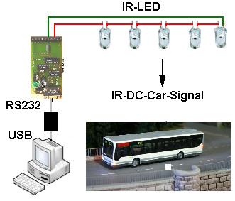
The PC-transmitter is a booster which can be connected directly to the RS232 port of a PC (or USB by convertor).
By doing so you do not need a DCC control station. The software you are using must support the DC-Car PC-Transmitter!
Software which do support:
Windigipet,
Traincontroller
and
Rocrail
The IR emitters, 5x IR LED connected in series, can be installed on the ceiling. Thus, the vehicle can be reached almost everywhere.
To use the PC Transmitter, the vehicle must have the optional LCIR.
This requires the vehicle decoder DC07 or DC08 with the right CV setting.
e.g. CV21 = 24 for the DC-Car-PC transmitter with WinDigipet
Functions
Since 2009 the DC-CAR system is supported by WinDigipet.
Currently 10 functions are possible.
This functions can be executed:
- F0 Headlight
- F1 Left indicator
- F2 Right indicator
- F3 Distance control from / to
- F4 Reed switch off / on
- F5 Blue light (4 blue lights on the roof)
- F6 Flashers (double flash in the grille)
- F7 Light 2
- F8 Light 3
- F9 Light 4 (if enabled via CV separated from Light 3)
Instructions
The indicator of the transmitter will only flash when functions are changed.
Therefore, different operation display on the PC and the condition of the vehicle after switching from one another!
The range of the transmitter is the same as the DC-Car-Booster: a maximum of 7 meters.
It depends on the incorporation of the optional needed LCIR in the model. Best is the reception on the passenger seat.
White plastic can be transparent to IR light. So from the outside, no change can be seen.
Command Set
see Command set
Error
- The serial sections of the computer was incorrectly selected. Often there are 2 or more.
- For USB adapter or USB ports are the drivers missing or incorrectly installed.
In the operating system, the interface needs to be displayed.
- In the Software as WinDigipet must be installed interface under 16th
- The polarity of the power supply Note Minus = mass.
- Eighth case of several model railway transformer s to Synchronizing.
- The resistance for the IR-LED is designed for up to 5 IR LED in series.
- The voltage of 11-14 volts = enough for 4 IR LED 16-18 VOLT ~ enough for 5 IR-LED.
(There the rectifier has been replaced with a diode in order to reduce the heat generation)
To test only one IR-LED can temporarily be used.
- For the PC transmitter or DC-Car-Booster other IR LEDs are needed from the function module.
- Note: If an IR LED defect in the chain is no function possible.
By bridging a defective LED can be determined.
Other errors See LCIR
