Difference between revisions of "DC-Car-Booster"
m (→Betrieb) |
m |
||
| (41 intermediate revisions by 2 users not shown) | |||
| Line 1: | Line 1: | ||
| − | [[File: | + | [[File:Booster-Prinzip2.jpg|330px|right]] |
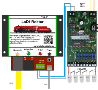
| − | == | + | [[File:LoDi-DC-Car-LCIR-Booster.png|330px|right|thumb|With iTrain or Wingigipet up 2018/1c|link=DC-Car-LoDi-Booster]] |
| − | + | ==Function== | |
| − | + | A '''DC-Car-Booster''' modulates the data signal of a DCC control station and transmits it via the IR LEDs.<br> | |
| − | + | This way of transmitting increases the range. Theoretically, transmission is possible up to 7 meters.<br> | |
| + | In order to ensure that the IR LEDs can control the cars, they should be mounted on the ceiling.<br> | ||
| + | The cars must have the optional LCIR receiver installed and it must be activated by CV21=4<br> | ||
| − | + | As a result, 7 x 5 = 35 LED can be connected. That's enough for about 35 square meters layout size. <br> | |
| − | + | [[File:DCC_Booster_Bestueckungsplan.gif|480px ]] upto 2013<br> | |
| − | + | [[File:DCC_Booster-2013.png|480 px]] from 2013<br> | |
| − | + | ||
| − | + | ||
| − | + | ||
| − | + | ||
| − | + | ||
| − | + | ||
| − | + | ||
| − | + | ||
| − | + | ||
| − | + | ||
| − | + | ||
| − | + | ||
| − | + | ||
| − | + | ||
| − | + | ||
| − | + | ||
| − | + | ||
| − | + | ||
| − | + | ||
| − | + | ||
| − | + | ||
| − | + | ||
| − | + | ||
| − | [[File:DCC_Booster_Bestueckungsplan.gif|480px ]] | + | |
| − | [[File:DCC_Booster-2013.png|480 px]] | + | |
[[File:Booster-Anschluss-Reihe.png|600px]]<br> | [[File:Booster-Anschluss-Reihe.png|600px]]<br> | ||
| − | == | + | == Operation == |
| − | + | By DC-Car-Booster, the vehicles can be controlled over a longer distance. <br> | |
| − | + | It is operated at 12-16 volts AC or DC. <br> | |
| − | + | The digital input is connected to the track connection (main track) of a DCC control station. <br> | |
| − | + | All outputs together can be loaded with 1 Ampere. <br> | |
| − | + | At each of the 7 outputs a chain of up to 5 infrared LEDs can be connected, ie a total of 35 LEDs <br> | |
| + | On the DC-Car-Booster is a control LED. This lights up when a DCC signal has been detected. <br> | ||
| + | In cooperation with an Intellibox or Twin Center is lit permanently. <br> | ||
| + | Together with other systems or in multiprotocol these may flash irregularly. <br> | ||
| + | If the DCC signal fails, the booster sends a stop signal to all the cars and the indicator flashes. <br> | ||
<br> | <br> | ||
| − | + | To use the DC-Car Booster, an additional [[LCIR | remote receiver]] must be installed in each vehicle. <br> | |
| − | + | By programming the CV21 this additional receiver is activated: <br> | |
| − | + | * No [[LCIR | LongControlIR]] (LCIR) operation CV21 = 0 <br> | |
| − | + | There are no signals from the [[LCIR | LongControlIR]] received (LCIR). | |
| + | * DC-Car-Booster CV21 = 4 | | ||
| + | The '' 'DC-Car-Booster' '' is easily connected to the track (main track) which is connected to the digital control station.<br> | ||
<br> | <br> | ||
| − | + | '' 'WARNING: The CV21 in the towing vehicle and the trailer Decoder must always have the same value. Otherwise, driving the trailer decoder stops working. '' '<br> | |
| − | + | ||
| − | + | ||
| − | + | ||
| − | + | ||
| − | + | ||
| − | + | ||
<br> | <br> | ||
| − | |||
<br> | <br> | ||
| + | |||
| + | == CV programming disabled == | ||
| + | There are no CV settings from the DC-Car-Booster transferred to the car. <br> | ||
| + | This feature was removed for safety's sake, because it came to unwanted programming of vehicles using the same DCC address. A programming transmitted along the rails should only be made by short range IR transmission via a Progset, this IR-LED transmitsthe data directly on the track or on the CV-Programmer. <br> | ||
| + | But if you want to programm by DC-Car Booster you have to ground PIN 28 of the processor by a bridge or jumper on the board. Alternatively, you can also use a switch. <br> | ||
<br> | <br> | ||
| + | '' 'NOTE: When you perform a reset, ALL vehicles in range of the transmitter are resetted!' '' <br> | ||
| + | [[CV-List]] | ||
| − | == | + | == Extension for booster or PC transmitter == |
| − | + | [[File:DCC_Booster_Bestueckungsplan.gif|480px ]]<br> | |
| − | + | [[File:Booster_Erweiterung2.png|300px|right ]]<br> | |
| − | + | [[File:Booster_Erweiterung2text.jpg|300px ]]<br> | |
| − | + | Since not 2 Booster may irradiate a car at the same time, the controller can be extended only by an amplifier. <br> | |
| − | + | ||
| − | [[ | + | |
| − | + | ||
| − | + | ||
| − | + | ||
<br> | <br> | ||
| − | + | For further 7 chains <br> | |
| − | + | with 5 LED <br> | |
| − | + | must be installed all odds. <br> | |
<br> | <br> | ||
| − | + | To connect the modules to high-quality cables are used most shilded cable. <br> | |
| − | + | The lines of the IR LED should be with Litzekabel and as short as possible. <br> | |
| − | + | With bell wire (rigid wires) may falsify the data. <br> | |
| + | '''[[DC-Car-LoDi-Booster]]'''<br> | ||
[[Category:DC-Car-System]] | [[Category:DC-Car-System]] | ||
[[Category:Software]] | [[Category:Software]] | ||
| − | [[Category: | + | [[Category:Errorlist]] |
| + | [[Category:Index_UK]] | ||
| + | [[Category:Index_US]] | ||
Latest revision as of 23:45, 22 April 2019

Function
A DC-Car-Booster modulates the data signal of a DCC control station and transmits it via the IR LEDs.
This way of transmitting increases the range. Theoretically, transmission is possible up to 7 meters.
In order to ensure that the IR LEDs can control the cars, they should be mounted on the ceiling.
The cars must have the optional LCIR receiver installed and it must be activated by CV21=4
As a result, 7 x 5 = 35 LED can be connected. That's enough for about 35 square meters layout size.
 upto 2013
 from 2013

Operation
By DC-Car-Booster, the vehicles can be controlled over a longer distance.
It is operated at 12-16 volts AC or DC.
The digital input is connected to the track connection (main track) of a DCC control station.
All outputs together can be loaded with 1 Ampere.
At each of the 7 outputs a chain of up to 5 infrared LEDs can be connected, ie a total of 35 LEDs
On the DC-Car-Booster is a control LED. This lights up when a DCC signal has been detected.
In cooperation with an Intellibox or Twin Center is lit permanently.
Together with other systems or in multiprotocol these may flash irregularly.
If the DCC signal fails, the booster sends a stop signal to all the cars and the indicator flashes.
To use the DC-Car Booster, an additional remote receiver must be installed in each vehicle.
By programming the CV21 this additional receiver is activated:
- No LongControlIR (LCIR) operation CV21 = 0
There are no signals from the LongControlIR received (LCIR).
- DC-Car-Booster CV21 = 4 |
The 'DC-Car-Booster' is easily connected to the track (main track) which is connected to the digital control station.
'WARNING: The CV21 in the towing vehicle and the trailer Decoder must always have the same value. Otherwise, driving the trailer decoder stops working. '
CV programming disabled
There are no CV settings from the DC-Car-Booster transferred to the car.
This feature was removed for safety's sake, because it came to unwanted programming of vehicles using the same DCC address. A programming transmitted along the rails should only be made by short range IR transmission via a Progset, this IR-LED transmitsthe data directly on the track or on the CV-Programmer.
But if you want to programm by DC-Car Booster you have to ground PIN 28 of the processor by a bridge or jumper on the board. Alternatively, you can also use a switch.
'NOTE: When you perform a reset, ALL vehicles in range of the transmitter are resetted!'
CV-List
Extension for booster or PC transmitter


Since not 2 Booster may irradiate a car at the same time, the controller can be extended only by an amplifier.
For further 7 chains
with 5 LED
must be installed all odds.
To connect the modules to high-quality cables are used most shilded cable.
The lines of the IR LED should be with Litzekabel and as short as possible.
With bell wire (rigid wires) may falsify the data.