Difference between revisions of "XT-Modul"
m (1 revision imported) |
|||
| (43 intermediate revisions by 2 users not shown) | |||
| Line 1: | Line 1: | ||
| − | + | [[file: Xt baustein.png | 225px | thumb |right| XT module to be mounted under the layout<br>click for video|link=https://www.youtube.com/watch?v=yC55IYEI6MY&list=PL5Ahyv-8Ps7-67U3pxK7n71DMFiWVEDYY&index=7]]<br> | |
| − | [[ | + | == Basics DC-Car-XT == |
| − | <br> | + | |
| − | + | ||
| − | + | XT means Extensions and describes the way that vehicles which are equipped with a DC-Car decoders actively transmit data. <br> | |
| − | + | Our idea was to develop a module, which on one hand gives the hobby modeller the opportunity to perform a simple automated traffic, | |
| − | + | without to deal with complicated controls or software. <br> | |
| − | + | On the other hand should also the advanced modelers get a chance to implement comprehensive control procedures and scenarios using a control software and resorting to specific vehicle data, download which are provided to you by the vehicles themselves. <br> | |
| − | + | There are countless applications feasible, what we would like to mention a few below: <br> | |
| − | + | * Emergency vehicles turn their way even free (driving through red lights) <br> | |
| + | * Overtaking of vehicles (in conjunction with the DC-Car-Lane Departure Warning) <br> | ||
| + | * Control of turn outs by evaluating the indicators (automatically stears itself into the direction in which the vehicle is flashing) <br> | ||
| + | * Control of a bus stop (bus turns the switch itself) <br> | ||
| + | * Sorting of vehicles (trucks may not enter the downtown traffic) <br> | ||
| + | * Sorting of vehicles with empty battery directions a loading station in conjunction with a software is a fully automatic charging possible) <br> | ||
<br> | <br> | ||
| − | + | This is all done with information that is sent from the vehicle via an infrared connection to the XT module. <br> | |
| − | + | To do this in a vehicle DC-Car decoders (from DC07 / DC08) have been mounted. <br> | |
| − | + | Is transmitted the following information: <br> | |
| − | + | #Vehicle number <br> | |
| − | + | #Vehicle type<br> | |
| − | + | #Status of indicators left <br> | |
| − | + | #Status of indicators right <br> | |
| + | #Status of hazard lights <br> | ||
| + | #Status of front flashers <br> | ||
| + | #Status of battery <br> | ||
<br> | <br> | ||
| − | + | The DC-Car-XT module is supplied as a ready-built module and has the dimensions 68mm x 57mm x 22mm. <br> | |
| − | + | It is designed so that it can be independently installed and operated. <br> | |
| − | + | For example, just below the point where the desired action to take. <br> | |
<br> | <br> | ||
| − | + | The XT module is available in our DC-Car-Shops. <br> | |
| − | + | ||
| − | + | ||
| − | + | ||
| − | + | ||
| − | + | ||
| − | + | ||
| − | + | ||
| − | + | ||
| − | + | ||
| − | + | ||
| − | + | ||
| − | + | ||
| − | == | + | == Transmit routine of the DC-Car Decoder == |
| − | + | Basic requirement for sending information is a vehicle decoder DC07 or DC08. <br> | |
| − | + | The vehicle decoder generation of D05, DC04 and older are to unable. <br> | |
| − | + | The vehicle decoder sends via an infrared LED which is connected to the MF5 or it send via IR LEDs at the back of the car (same as the ones for the distance control). | |
| − | + | <table><tr><td> | |
| − | + | [[File: xt_dc07.png | 125px | Decoder DC07]] | |
| − | [[ | + | |
<br> | <br> | ||
| − | + | When DC07, a series resistor must be added. <br> | |
| + | The resistance value should be 100 ohms.</td><td> | ||
<br> | <br> | ||
| + | [[File: xt_dc08.png | 175px | Decoder DC08]] | ||
<br> | <br> | ||
| − | + | The DC08 has the resistor already on the board. <br> | |
| + | Here the LED can be connected directly. </td></tr></table><br> | ||
| + | As infrared LED, you can use the standard 0603-IR-LEDs, the distance control. <br> | ||
| + | The following data is sent: <br> | ||
<br> | <br> | ||
| − | + | Vehicle number <br> | |
| + | Vehicle type <br> | ||
| + | <br> Status of the left turn signal | ||
| + | <br> Status of the right turn signal | ||
| + | Status of hazard lights <br> | ||
| + | Status of the front flashers <br> | ||
| + | Status of the battery <br> | ||
<br> | <br> | ||
| − | + | ||
| − | + | == Infrared transmitter - receiver distance == | |
| + | [[file: xt_leitpfosten.png | 250px | thumb |]] | ||
| + | In order to receive the data the transmitter LED, a phototransistor is necessary. Again, you can rely on the proven DC-Car Components. <br> | ||
| + | Simply use a phototransistor of the DC-Car-distance control. This can be well camouflaged mounted at the roadside. <br> | ||
| + | For example: to trees, shrubs, buildings, vehicles or delineator posts. <br> | ||
<br> | <br> | ||
| − | + | These delineators (pictured right) can be purchased in the shop ready for connection to the XT module. <br> | |
| − | + | The distance between the emitting diode and fototransistor should not exceed 5 cm. <br> | |
| − | + | Thus reliable transmission is guaranteed even at high speeds. <br> | |
| − | + | The fototransistor is connected with two wires to the DC-Car-XT module. <br> | |
| − | + | [[File: Xt_sende_ir1.png | 250px | thumb | right | Location of transmitter diode]] | |
| − | + | ||
| − | + | ||
<br> | <br> | ||
| − | |||
| − | |||
| − | |||
| − | |||
| − | |||
<br> | <br> | ||
| − | + | There are various ways and approaches how to design the IR transmission. <br> | |
| − | + | For example, you can place the IR LED mounted on the underside of your vehicle and hide the fototransistor in the roadway. <br> | |
| − | + | Advantage this type of installation is that at the moment of evaluation extraneous light can be virtually ruled out because the vehicle so completely covering the fototransistor. <br> | |
| − | + | ||
| − | + | ||
<br> | <br> | ||
<br> | <br> | ||
| + | Drawback is that it can be obscured by dust, impurities, etc. of the fototransistor. In addition, the transmission LED must be positioned very accurately, downwart due to the small distance between bottom and road. <br> | ||
<br> | <br> | ||
<br> | <br> | ||
| + | Another variant is the installation on the right side of the vehicle at the side hight. <br> | ||
| + | In systems with links driving the assembly should naturally take place on the left side. <br> | ||
<br> | <br> | ||
| − | + | Due to the larger spacing between the transmitter and the receiver, the tolerance in the mounting height is significantly larger and thus easier to accomplish the installation. <br> | |
| − | + | ||
| − | + | ||
<br> | <br> | ||
<br> | <br> | ||
| − | + | ||
| − | + | == DC-Car-XT module == | |
| + | [[File: xt_baustein.png | 225px | thumb | XT chip to be mounted under the plate]] | ||
| + | The DC-Car-XT module is the counterpart to the DC-Car decoders. <br> | ||
| + | It is primarily used as a standalone controller to perform individually adjustable features that are desired by the evaluation. <br> | ||
| + | In addition, it converts the received signals and provides them in different formats for further processing. <br> | ||
| + | For example, to be fed into a feedback bus or for evaluation with software on a PC. <br> | ||
<br> | <br> | ||
<br> | <br> | ||
| − | + | The following functions are currently available: | |
| − | + | ||
| − | + | ||
| − | + | ||
| − | + | ||
| − | + | ||
| − | + | ||
| − | + | ||
| − | + | ||
| − | + | ||
| − | + | ||
| − | + | ||
| − | + | ||
| − | + | ||
| − | + | ||
| − | + | ||
| − | + | ||
| − | + | ||
| − | + | ||
| − | + | ||
| − | + | ||
| − | + | ||
| − | + | ||
| − | + | ||
| − | + | ||
| − | + | ||
| − | + | ||
| − | + | ||
| − | + | ||
| − | + | ||
| − | + | ||
| − | + | ||
| − | + | ||
| − | + | ||
| − | + | ||
| − | + | ||
| − | + | ||
<br> | <br> | ||
| + | #Control a (turn out) servo (2-, 3- or 4-way selectable) <br> | ||
| + | #Switch a contact to ground / GND <br> | ||
| + | #Send a freely selectable DC-Car-infrared commands <br> | ||
<br> | <br> | ||
<br> | <br> | ||
| + | You can select whether the respective function are resetted after a certain time or trigger by a reed contact. <br> | ||
<br> | <br> | ||
| + | ===Pin assignment === | ||
| + | [[File: xt_anschluss.png | 550px | Description of the XT terminal module]] | ||
<br> | <br> | ||
| − | === | + | === Connection Description=== |
| − | [[ | + | [[Image: Xt_usb.jpg | 300px | thumb | right | Powered via USB]] |
<br> | <br> | ||
| − | + | Power supply: <br> | |
| − | + | The DC-Car-XT module requires for operation a DC voltage of 5V / 500mA. <br> | |
| − | + | These can be supplied either via the screw terminal block or the mini-USB port. <br> | |
| − | + | The USB connector is only used for this purpose. It can through this terminal while being received or transmitted any data! <br> | |
<br> | <br> | ||
| − | '''*LED | + | '''* LED display blue (right) and green (left)''' in |
| − | + | The green LED indicates the presence of the 5V power supply. <br> | |
| − | + | The blue LED lights up for the period by a valid signal was received. <br> | |
<br> | <br> | ||
| − | '''* | + | '''* Reed contact''' in |
| − | + | This connector is used to reset a tripped function. <br> | |
| − | + | For example, thus turning off the switch contact or reset a Servo turn out again. <br> | |
| − | + | The reed contact must be connected to ground / GND. <br> | |
<br> | <br> | ||
| − | '''*Fototransistor (+ | + | '''* Fototransistor (+ and -)''' in |
| − | + | Here the fototransistor is connected to receive the data with the correct polarity. <br> | |
<br> | <br> | ||
| − | '''* | + | '''* Infrared LED''' out |
| − | + | Here the negative pole (cathode) is connected an infrared LED which emits a freely selectable DC-Car-infrared command. <br> | |
| − | + | For example, stop, turn signals to or the assignment of a lane for the Lane Departure Warning System. <br> | |
| − | + | In addition, can be set the time how long the IR command is sent. <br> | |
| − | '' | + | '' Warning: A series resistor is already on the board and externally must not be added! '' |
<br> | <br> | ||
| − | '''* | + | '''* Switching transistor''' in |
| − | + | Here you can connect a relay or any other consumers, which is turned on. <br> | |
| − | + | Please note that a ground connection between the XT module and the control electronics of the respective consumer has to be made. <br> | |
| − | + | For example, you can thus go to the switch actuator of a servo decoder or traffic light decoder and thus trigger functions. <br> | |
<br> | <br> | ||
| − | '''* | + | '''* Servo Connection''' out |
| − | + | The power connector is used to directly drive a model servo through the XT module. You can connect all conventional small servomotor here. <br> | |
| − | + | Please observe the correct connection sequence, as these may differ among the different manufacturers. <br> | |
<br> | <br> | ||
| − | '''* | + | '''* Connection for CV-Programmer''' in |
| − | + | This 8-pin jack is used to connect the module to the DC-Car CV-Programmer. <br> | |
| − | + | This is required in order to configure the software "CV-Programmer" the XT module individually. <br> | |
| − | + | It is the same program and hardware which is also used to change the CVs of the DC-Car decoders. <br> | |
| − | + | The software (version 478.XT or higher) you can download free from our website. The hardware is available in the shop. <br> | |
<br> | <br> | ||
| − | '''* | + | '''* Vehicle data series and 5-pin socket 8-pin and''' out |
| − | + | These connectors are used to route the received data to a feedback bus or software. <br> | |
| − | + | They are either serial (connection on the terminal strip) or binary (8/5-pin female) output. <br> | |
| − | == | + | == Connecting the XT module with the PC == |
<br> | <br> | ||
| − | ''' | + | '''The XT module is an independent unit. You need to operate a PC. '''In |
| − | ''' | + | '''This is only for one-time configuration of the XT module before the operation necessary.''' In |
| − | ''' | + | '''To make these settings on the XT module, the interface device CV-Programmer XT "is necessary.''' In |
| − | ''' | + | '''This can be purchased in the shop.''' In |
<br> | <br> | ||
| − | + | Please note that the "CV-Programmer USB" can not be used here. <br> | |
| − | + | The USB port which is used for electricity connected programmer not provide enough power to a possibly connected it to operate servo. <br> | |
| − | + | If you do not run power, naturally also works the normal CV-Programmer USB. <br> | |
<br> | <br> | ||
| − | # | + | # Connect the 8-pin connector of the "CV-Programmer" with the left 8-pin connector of the XT module. The marking of the connector must point to the left edge of the case. <br> |
| − | # | + | # Then press the button (hold) on the programmer and then turn on the Programmer. If the blue LED flashes on XT module, you can release the button. <br> |
| − | # | + | # Start the included PC program "CV-Programmer". Under "Serial port" the COM port to which the hardware "CV-Programmer" is connected to your PC. <br> |
| − | # | + | # Now press "Read all CVs from the vehicle" button. Well read and display all the CVs of XT module. <br> |
| − | # In | + | # In the menu bar, you can read the item "receiver function" now. <br> |
<br> | <br> | ||
| − | + | Please note that you are using a power supply / power supply with min. 500mAh, otherwise the may already connected servo pulls the voltage down and the XT module can not be achieved by the PC. <br> | |
| − | + | Alternatively, you can also connect the servo subsequently. This is due to the practical 3-pin plug connection is no problem. <br> | |
<br> | <br> | ||
| − | === | + | === General Function=== |
| − | + | In the first step you have to define how and what to evaluate the XT module and is further processed. <br> | |
| − | + | The following options are available: <br> | |
| − | ◊ | + | ◊ Light Function (incl. low battery)<br> or <br> |
| − | ◊ | + | ◊ Genus evaluation <br> or <br> |
| − | ◊ | + | ◊ Vehicle number evaluation <br> |
<br> | <br> | ||
| − | + | Not yet available, the evaluation of: <br> | |
| − | ◊ | + | ◊ genus combined with vehicle number <br> |
| − | + | and <br> | |
| − | ◊ | + | ◊ genus and vehicle number separated <br> evaluate |
| − | + | Therefore, these are still grayed out. | |
<br> | <br> | ||
| − | + | The light function is separately in the menu item "light function" is enabled. <br> | |
<br> | <br> | ||
| − | + | Click to set the desired function, first on the menu item "receiver function" and select "General" from. <br> | |
| − | + | This opens another window. <br> | |
| − | + | Now select the desired mode by clicking on the item. <br> | |
<br> | <br> | ||
| − | + | Now you need to define how the provision is to take place. The provision can be done by: <br> | |
<br> | <br> | ||
| − | ◊ | + | ◊ timing (defined in CV 97) <br> |
| − | ◊ Reed/ | + | ◊ Reed / switch contact or Hall sensor <br> |
<br> | <br> | ||
| − | + | If the servo after the command has arrived back in the starting position, the power supply can be switched off <br> | |
| − | + | This prevents unnecessary power consumption and the "servo jitter" which can be heard in some servos. <br> | |
| − | + | Simply select the menu item "Servo off after carrying out the rotary movement". <br> | |
<br> | <br> | ||
| − | + | After completing the configuration click on the button "Save CV98". A confirmation query whether you really want to activate the vehicle number / genre analysis as a parallel evaluation with the light function is not possible. You need to confirm. | |
<br> | <br> | ||
| − | === | + | === Define lighting functions=== |
| − | + | XT-light function of the module has the purpose to execute sequences or actions, which is controlled by the illumination of the vehicles. <br> | |
| − | + | For example, a vehicle with a set left turn the switch on the left. <br> | |
| − | + | Or an emergency vehicle with activated front flashers triggers a stop signal for all other vehicles at an intersection. <br> | |
<br> | <br> | ||
| − | + | There are evaluated: <br> | |
| − | ◊ | + | ◊ Left indicator <br> |
| − | ◊ | + | ◊ Right indicator <br> |
| − | ◊ Warnblinker<br> | + | ◊ Warnblinker <br> |
| − | ◊ | + | ◊ Front flashers <br> |
| − | ◊ | + | ◊ Battery warning <br> |
<br> | <br> | ||
| − | + | Click to set the desired function, first on the menu item "receiver function" and choose "light function". This opens another window. <br> | |
<br> | <br> | ||
| − | + | Now select the light function, which is to be evaluated. After you decide which function is to be performed upon successful evaluation. <br> | |
<br> | <br> | ||
| − | + | These are available: | |
| − | + | ||
| − | + | ||
<br> | <br> | ||
| − | + | ◊ Servo soft spots <br> | |
| + | ◊ Transistor switch (trigger contact) <br> | ||
| + | ◊ Freely selectable infrared command post <br> | ||
<br> | <br> | ||
| − | + | All three functions can be performed independently by the XT module. You must connect the corresponding switch actuators with the XT module. <br> | |
| − | + | ||
| − | + | ||
| − | + | ||
<br> | <br> | ||
| − | + | After completing the configuration click on the button "CV's save". <br> | |
| − | + | A confirmation query whether you really want to activate the function as a parallel evaluation with vehicle number / genus is not possible. <br> | |
| − | + | You need to confirm. <br> | |
| + | The software will now transfer the configuration to the XT module. <br> | ||
<br> | <br> | ||
| − | |||
| − | |||
| − | |||
| − | |||
| − | |||
| − | |||
| − | |||
| − | |||
| − | + | === Adjust servo function and define branch art=== | |
| − | + | The XT module is able to control a servo. It is therefore not necessary to purchase a separate servo decoder. <br> | |
| − | + | To use this feature, you must adjust the XT module to your servo. <br> | |
| − | + | ||
| − | + | ||
<br> | <br> | ||
| − | + | Just click the menu item "receiver function" to the point "switching function". <br> | |
| + | Now you can set whether you want to turn a 2-, 3- or 4-way switch. <br> | ||
| + | After you click "Save CV39" on the button, the setting will be transferred to the XT module and acknowledged. <br> | ||
| + | '''Note: When activating the lighting function, a 3-way crossover is automatically set.''' In | ||
<br> | <br> | ||
| + | In the next step, a mandatory query. Here you have to define the starting position, in which the servo when turning on the XT module, download | ||
| + | returns and after movement function. <br> | ||
| + | This setting procedure is automatic, you only need to follow the onscreen instructions. <br> | ||
| − | + | Now select the menu item "Set Servo" the point "receiver function". <br> | |
| − | + | Depending on the selected branch art, you will see now 2, 3 or 4 sliders. <br> | |
| − | + | With these sliders you can now set the servo end positions that are applicable for your switch. <br> | |
| − | + | ||
| − | + | ||
| − | + | ||
| − | + | ||
| − | + | ||
| − | + | ||
| − | + | ||
| − | + | ||
| − | + | ||
| − | + | ||
| − | + | ||
| − | + | ||
| − | + | ||
| − | + | ||
| − | + | ||
| − | + | ||
| − | + | ||
<br> | <br> | ||
| − | + | By clicking the point on the right side behind each entry you can move the servo to the appropriate position. <br> | |
<br> | <br> | ||
| − | + | By clicking on the "Save" button, the set data is transmitted to the XT module and thus the servo configuration is complete. <br> | |
| − | + | ||
| − | + | ||
<br> | <br> | ||
| − | + | ||
| + | === Evaluation of the genus=== | ||
| + | The genus is used to distinguish different types of vehicles. <br> | ||
| + | The genus has to be set in each DC-Car vehicle decoder in the CV100. <br> | ||
| + | There are 15 genres available: <br> | ||
| + | * 0 = General <br> | ||
| + | * 1 = truck short<br> | ||
| + | * 2 = truck long<br> | ||
| + | * 3 = truck with trailer <br> | ||
| + | * 4 = tractor with trailer <br> | ||
| + | * 5 = tractor <br> | ||
| + | * 6 = agriculture (tractor, etc.) <br> | ||
| + | * 7 = freely usable <br> | ||
| + | * 8 = vans (Sprinter etc.) <br> | ||
| + | * 9 = car <br> | ||
| + | * 10 = emergency vehicle with convoy function [stations the distance control during stop "OFF"] <br> | ||
| + | * 11 = emergency vehicle [stations the distance control during stop "ON"] <br> | ||
| + | * 12 = freely usable <br> | ||
| + | * 13 = garbage truck, post, etc. <br> | ||
| + | * 14 = Bus [stations the distance control during stop "OFF"] <br> | ||
| + | * 15 = Bus [stations the distance control during stop "ON"] <br> | ||
<br> | <br> | ||
| − | + | A total of 8 memory locations are available for the genus evaluation purposes, ie the maximum amount of 8 genus can be evaluate by XT module. <br> | |
<br> | <br> | ||
| − | + | '' Example: '' in | |
| + | All emergency vehicles of the genus 10 are evaluated. The XT module sends by detection an IR stop command what will stops all other vehicles at an intersection. <br> | ||
| + | After 5 seconds, the stop command will be canceled and all vehicles drive on. <br> | ||
<br> | <br> | ||
| − | + | Click to adjust the genus evaluation in the menu item to "receiver function", go to the point "Recognize" and then select "Analysis of the genus" from. It opens a new window. <br> | |
| − | + | ||
<br> | <br> | ||
| − | + | Place 1-8 determines which species will be evaluated on which memory. <br> | |
| − | + | ||
| − | + | ||
| − | + | ||
<br> | <br> | ||
| − | + | Activation of the desired function is performed by double-clicking in the appropriate window. This corresponds <br> | |
| − | + | * 0 = disabled <br> | |
| + | * 1 = activated<br> | ||
| + | Available functions: <br> | ||
| + | ◊ Servo (incl. shutdown) <br> | ||
| + | ◊ Transistor switch (trigger contact) <br> | ||
| + | ◊ Freely selectable infrared command post <br> | ||
<br> | <br> | ||
| − | + | When activating the "Function Command" opens another window where you can select the DC-Car-infrared command. <br> | |
| + | With click on the button "Apply" to confirm your selection. <br> | ||
<br> | <br> | ||
| − | === | + | You have finished, click "Save". After that the module is configured and the data is transferred. <br> |
| − | + | ||
| − | + | === Evaluation of vehicle number=== | |
| − | + | The vehicle number is used to distinguish between different types of vehicles of the same genus. <br> | |
| + | It must be set in every DC-Car-vehicle decoder in the CV113. The vehicle numbers 0-31 can be set per species. <br> | ||
| + | The vehicle number has nothing to do with the DCC digital address. This is not evaluated by XT module! <br> | ||
<br> | <br> | ||
| − | + | A total of 8 memory locations for the evaluation of vehicle number available, ie You can evaluate up to 8 vehicle numbers through a parallel XT module. <br> | |
<br> | <br> | ||
| − | '' | + | '' Example: '' |
| − | + | All buses of the genus 14 are evaluated. However, it may travel to a specific station only buses with vehicle numbers 1, 4 and 6. <br> | |
| − | + | So The XT module switches upon detection of the corresponding vehicle numbers a power switch and only allows these buses drive into the station. <br> | |
| − | + | All other vehicles and buses run normally. After crossing a reed contact through the bus the switch is reset immediately. <br> | |
<br> | <br> | ||
| − | + | Click to adjust the vehicle number evaluation under the menu item to "receiver function", go to the point "Recognize" and then select "Analysis of vehicle numbers" from. <br> | |
| − | + | It opens a new window. <br> | |
<br> | <br> | ||
| − | + | Place 1-8 determines which species will be evaluated on which memory. <br> | |
<br> | <br> | ||
| − | + | Activation of the desired function is performed by double-clicking in the appropriate window. This corresponds <br> | |
| − | * 0 = | + | * 0 = disabled <br> |
| − | * 1 = | + | * 1 = enabled. <br> |
<br> | <br> | ||
| − | + | Available functions: <br> | |
| − | ◊ | + | ◊ Servo Soft filters (incl. Shutdown) <br> |
| − | ◊ | + | ◊ transistor switch (trigger contact) <br> |
| − | ◊ | + | ◊ freely selectable infrared command post <br> |
<br> | <br> | ||
| − | + | When activating the "Function Command" to open another window where you can select the DC-Car-infrared command. <br> | |
| − | + | With click on the button "Apply" to confirm your selection. <br> | |
<br> | <br> | ||
| − | + | You have finished, click "Save". After the module is configured and transmit the data. <br> | |
<br> | <br> | ||
| − | == | + | |
| − | [[ | + | == Connection to a feedback system or PC with software == |
| − | + | [[File: Xt rm bus anschluss.png | thumb | right | 200px]] | |
| + | To enter the data received from XT module data in a feedback bus or PC for further processing, there are three possibilities: <br> | ||
| + | 1) Serial Output<br> | ||
| + | * The received data is issued as a serial signal at pin "serial"<br> | ||
| + | 2.) Switching Output <br> | ||
| + | * The switching output can be connected to the input of a feedback decoder (S88®, Loconet® etc.) and thus quite simply more switching operations or the visualization in a model railroad control program (eg WinDigipet®, Traincontroller®) be achieved <br> | ||
| + | 3.) Binary signal <br> | ||
| + | * The XT module provides a total of 12 outputs are available, of which the received vehicle type and the vehicle number are output in binary coding. <br> | ||
| + | * A valid signal is defined by a check bit and output at "valid". <br> | ||
<br> | <br> | ||
| − | + | '' Example: '' | |
| − | + | The vehicle with the car number 9 and genus 3 is detected, it takes place on the following outputs a signal: <br> | |
| − | + | * Registration number is 1 + 8 = 9 <br> | |
| − | + | * Generic value 1 + value 2 = 3 <br> | |
| − | + | == Video == | |
| − | + | [https://www.youtube.com/watch?v=yC55IYEI6MY&list=PL5Ahyv-8Ps7-67U3pxK7n71DMFiWVEDYY&index=7 Video]<br> | |
| − | + | ||
| − | + | ||
| − | + | ||
| − | + | ||
| − | '' | + | |
| − | + | ||
| − | + | ||
| − | * | + | |
| − | * | + | |
| − | <br> | + | |
| − | + | ||
| − | [[ | + | [[Category: DC-Car-System]] |
| − | [[ | + | [[Category: Traffic_control]] |
| − | [[ | + | [[Category: Roadsystem]] |
| − | [[ | + | [[Category: Advanced control]] |
| − | [[ | + | [[Category: IR-Request]] |
| − | [[ | + | [[Category: Feedback systems]] |
| − | [[ | + | [[Category: CVlist]] |
| − | [[ | + | [[Category: Download]] |
| + | [[Category: XT_modul]] | ||
| + | [[Category: Index_UK]] | ||
| + | [[Category: Index_US]] | ||
Latest revision as of 20:11, 15 September 2018
Contents
Basics DC-Car-XT
XT means Extensions and describes the way that vehicles which are equipped with a DC-Car decoders actively transmit data.
Our idea was to develop a module, which on one hand gives the hobby modeller the opportunity to perform a simple automated traffic,
without to deal with complicated controls or software.
On the other hand should also the advanced modelers get a chance to implement comprehensive control procedures and scenarios using a control software and resorting to specific vehicle data, download which are provided to you by the vehicles themselves.
There are countless applications feasible, what we would like to mention a few below:
- Emergency vehicles turn their way even free (driving through red lights)
- Overtaking of vehicles (in conjunction with the DC-Car-Lane Departure Warning)
- Control of turn outs by evaluating the indicators (automatically stears itself into the direction in which the vehicle is flashing)
- Control of a bus stop (bus turns the switch itself)
- Sorting of vehicles (trucks may not enter the downtown traffic)
- Sorting of vehicles with empty battery directions a loading station in conjunction with a software is a fully automatic charging possible)
This is all done with information that is sent from the vehicle via an infrared connection to the XT module.
To do this in a vehicle DC-Car decoders (from DC07 / DC08) have been mounted.
Is transmitted the following information:
- Vehicle number
- Vehicle type
- Status of indicators left
- Status of indicators right
- Status of hazard lights
- Status of front flashers
- Status of battery
The DC-Car-XT module is supplied as a ready-built module and has the dimensions 68mm x 57mm x 22mm.
It is designed so that it can be independently installed and operated.
For example, just below the point where the desired action to take.
The XT module is available in our DC-Car-Shops.
Transmit routine of the DC-Car Decoder
Basic requirement for sending information is a vehicle decoder DC07 or DC08.
The vehicle decoder generation of D05, DC04 and older are to unable.
The vehicle decoder sends via an infrared LED which is connected to the MF5 or it send via IR LEDs at the back of the car (same as the ones for the distance control).
|
|
|


As infrared LED, you can use the standard 0603-IR-LEDs, the distance control.
The following data is sent:
Vehicle number
Vehicle type
Status of the left turn signal
Status of the right turn signal
Status of hazard lights
Status of the front flashers
Status of the battery
Infrared transmitter - receiver distance

In order to receive the data the transmitter LED, a phototransistor is necessary. Again, you can rely on the proven DC-Car Components.
Simply use a phototransistor of the DC-Car-distance control. This can be well camouflaged mounted at the roadside.
For example: to trees, shrubs, buildings, vehicles or delineator posts.
These delineators (pictured right) can be purchased in the shop ready for connection to the XT module.
The distance between the emitting diode and fototransistor should not exceed 5 cm.
Thus reliable transmission is guaranteed even at high speeds.
The fototransistor is connected with two wires to the DC-Car-XT module.

There are various ways and approaches how to design the IR transmission.
For example, you can place the IR LED mounted on the underside of your vehicle and hide the fototransistor in the roadway.
Advantage this type of installation is that at the moment of evaluation extraneous light can be virtually ruled out because the vehicle so completely covering the fototransistor.
Drawback is that it can be obscured by dust, impurities, etc. of the fototransistor. In addition, the transmission LED must be positioned very accurately, downwart due to the small distance between bottom and road.
Another variant is the installation on the right side of the vehicle at the side hight.
In systems with links driving the assembly should naturally take place on the left side.
Due to the larger spacing between the transmitter and the receiver, the tolerance in the mounting height is significantly larger and thus easier to accomplish the installation.
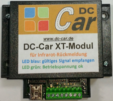
DC-Car-XT module

The DC-Car-XT module is the counterpart to the DC-Car decoders.
It is primarily used as a standalone controller to perform individually adjustable features that are desired by the evaluation.
In addition, it converts the received signals and provides them in different formats for further processing.
For example, to be fed into a feedback bus or for evaluation with software on a PC.
The following functions are currently available:
- Control a (turn out) servo (2-, 3- or 4-way selectable)
- Switch a contact to ground / GND
- Send a freely selectable DC-Car-infrared commands
You can select whether the respective function are resetted after a certain time or trigger by a reed contact.
Pin assignment

Connection Description

Power supply:
The DC-Car-XT module requires for operation a DC voltage of 5V / 500mA.
These can be supplied either via the screw terminal block or the mini-USB port.
The USB connector is only used for this purpose. It can through this terminal while being received or transmitted any data!
* LED display blue (right) and green (left) in
The green LED indicates the presence of the 5V power supply.
The blue LED lights up for the period by a valid signal was received.
* Reed contact in
This connector is used to reset a tripped function.
For example, thus turning off the switch contact or reset a Servo turn out again.
The reed contact must be connected to ground / GND.
* Fototransistor (+ and -) in
Here the fototransistor is connected to receive the data with the correct polarity.
* Infrared LED out
Here the negative pole (cathode) is connected an infrared LED which emits a freely selectable DC-Car-infrared command.
For example, stop, turn signals to or the assignment of a lane for the Lane Departure Warning System.
In addition, can be set the time how long the IR command is sent.
Warning: A series resistor is already on the board and externally must not be added!
* Switching transistor in
Here you can connect a relay or any other consumers, which is turned on.
Please note that a ground connection between the XT module and the control electronics of the respective consumer has to be made.
For example, you can thus go to the switch actuator of a servo decoder or traffic light decoder and thus trigger functions.
* Servo Connection out
The power connector is used to directly drive a model servo through the XT module. You can connect all conventional small servomotor here.
Please observe the correct connection sequence, as these may differ among the different manufacturers.
* Connection for CV-Programmer in
This 8-pin jack is used to connect the module to the DC-Car CV-Programmer.
This is required in order to configure the software "CV-Programmer" the XT module individually.
It is the same program and hardware which is also used to change the CVs of the DC-Car decoders.
The software (version 478.XT or higher) you can download free from our website. The hardware is available in the shop.
* Vehicle data series and 5-pin socket 8-pin and out
These connectors are used to route the received data to a feedback bus or software.
They are either serial (connection on the terminal strip) or binary (8/5-pin female) output.
Connecting the XT module with the PC
The XT module is an independent unit. You need to operate a PC. In
This is only for one-time configuration of the XT module before the operation necessary. In
To make these settings on the XT module, the interface device CV-Programmer XT "is necessary. In
This can be purchased in the shop. In
Please note that the "CV-Programmer USB" can not be used here.
The USB port which is used for electricity connected programmer not provide enough power to a possibly connected it to operate servo.
If you do not run power, naturally also works the normal CV-Programmer USB.
- Connect the 8-pin connector of the "CV-Programmer" with the left 8-pin connector of the XT module. The marking of the connector must point to the left edge of the case.
- Then press the button (hold) on the programmer and then turn on the Programmer. If the blue LED flashes on XT module, you can release the button.
- Start the included PC program "CV-Programmer". Under "Serial port" the COM port to which the hardware "CV-Programmer" is connected to your PC.
- Now press "Read all CVs from the vehicle" button. Well read and display all the CVs of XT module.
- In the menu bar, you can read the item "receiver function" now.
Please note that you are using a power supply / power supply with min. 500mAh, otherwise the may already connected servo pulls the voltage down and the XT module can not be achieved by the PC.
Alternatively, you can also connect the servo subsequently. This is due to the practical 3-pin plug connection is no problem.
General Function
In the first step you have to define how and what to evaluate the XT module and is further processed.
The following options are available:
◊ Light Function (incl. low battery)
or
◊ Genus evaluation
or
◊ Vehicle number evaluation
Not yet available, the evaluation of:
◊ genus combined with vehicle number
and
◊ genus and vehicle number separated
evaluate
Therefore, these are still grayed out.
The light function is separately in the menu item "light function" is enabled.
Click to set the desired function, first on the menu item "receiver function" and select "General" from.
This opens another window.
Now select the desired mode by clicking on the item.
Now you need to define how the provision is to take place. The provision can be done by:
◊ timing (defined in CV 97)
◊ Reed / switch contact or Hall sensor
If the servo after the command has arrived back in the starting position, the power supply can be switched off
This prevents unnecessary power consumption and the "servo jitter" which can be heard in some servos.
Simply select the menu item "Servo off after carrying out the rotary movement".
After completing the configuration click on the button "Save CV98". A confirmation query whether you really want to activate the vehicle number / genre analysis as a parallel evaluation with the light function is not possible. You need to confirm.
Define lighting functions
XT-light function of the module has the purpose to execute sequences or actions, which is controlled by the illumination of the vehicles.
For example, a vehicle with a set left turn the switch on the left.
Or an emergency vehicle with activated front flashers triggers a stop signal for all other vehicles at an intersection.
There are evaluated:
◊ Left indicator
◊ Right indicator
◊ Warnblinker
◊ Front flashers
◊ Battery warning
Click to set the desired function, first on the menu item "receiver function" and choose "light function". This opens another window.
Now select the light function, which is to be evaluated. After you decide which function is to be performed upon successful evaluation.
These are available:
◊ Servo soft spots
◊ Transistor switch (trigger contact)
◊ Freely selectable infrared command post
All three functions can be performed independently by the XT module. You must connect the corresponding switch actuators with the XT module.
After completing the configuration click on the button "CV's save".
A confirmation query whether you really want to activate the function as a parallel evaluation with vehicle number / genus is not possible.
You need to confirm.
The software will now transfer the configuration to the XT module.
Adjust servo function and define branch art
The XT module is able to control a servo. It is therefore not necessary to purchase a separate servo decoder.
To use this feature, you must adjust the XT module to your servo.
Just click the menu item "receiver function" to the point "switching function".
Now you can set whether you want to turn a 2-, 3- or 4-way switch.
After you click "Save CV39" on the button, the setting will be transferred to the XT module and acknowledged.
Note: When activating the lighting function, a 3-way crossover is automatically set. In
In the next step, a mandatory query. Here you have to define the starting position, in which the servo when turning on the XT module, download
returns and after movement function.
This setting procedure is automatic, you only need to follow the onscreen instructions.
Now select the menu item "Set Servo" the point "receiver function".
Depending on the selected branch art, you will see now 2, 3 or 4 sliders.
With these sliders you can now set the servo end positions that are applicable for your switch.
By clicking the point on the right side behind each entry you can move the servo to the appropriate position.
By clicking on the "Save" button, the set data is transmitted to the XT module and thus the servo configuration is complete.
Evaluation of the genus
The genus is used to distinguish different types of vehicles.
The genus has to be set in each DC-Car vehicle decoder in the CV100.
There are 15 genres available:
- 0 = General
- 1 = truck short
- 2 = truck long
- 3 = truck with trailer
- 4 = tractor with trailer
- 5 = tractor
- 6 = agriculture (tractor, etc.)
- 7 = freely usable
- 8 = vans (Sprinter etc.)
- 9 = car
- 10 = emergency vehicle with convoy function [stations the distance control during stop "OFF"]
- 11 = emergency vehicle [stations the distance control during stop "ON"]
- 12 = freely usable
- 13 = garbage truck, post, etc.
- 14 = Bus [stations the distance control during stop "OFF"]
- 15 = Bus [stations the distance control during stop "ON"]
A total of 8 memory locations are available for the genus evaluation purposes, ie the maximum amount of 8 genus can be evaluate by XT module.
Example: in
All emergency vehicles of the genus 10 are evaluated. The XT module sends by detection an IR stop command what will stops all other vehicles at an intersection.
After 5 seconds, the stop command will be canceled and all vehicles drive on.
Click to adjust the genus evaluation in the menu item to "receiver function", go to the point "Recognize" and then select "Analysis of the genus" from. It opens a new window.
Place 1-8 determines which species will be evaluated on which memory.
Activation of the desired function is performed by double-clicking in the appropriate window. This corresponds
- 0 = disabled
- 1 = activated
Available functions:
◊ Servo (incl. shutdown)
◊ Transistor switch (trigger contact)
◊ Freely selectable infrared command post
When activating the "Function Command" opens another window where you can select the DC-Car-infrared command.
With click on the button "Apply" to confirm your selection.
You have finished, click "Save". After that the module is configured and the data is transferred.
Evaluation of vehicle number
The vehicle number is used to distinguish between different types of vehicles of the same genus.
It must be set in every DC-Car-vehicle decoder in the CV113. The vehicle numbers 0-31 can be set per species.
The vehicle number has nothing to do with the DCC digital address. This is not evaluated by XT module!
A total of 8 memory locations for the evaluation of vehicle number available, ie You can evaluate up to 8 vehicle numbers through a parallel XT module.
Example:
All buses of the genus 14 are evaluated. However, it may travel to a specific station only buses with vehicle numbers 1, 4 and 6.
So The XT module switches upon detection of the corresponding vehicle numbers a power switch and only allows these buses drive into the station.
All other vehicles and buses run normally. After crossing a reed contact through the bus the switch is reset immediately.
Click to adjust the vehicle number evaluation under the menu item to "receiver function", go to the point "Recognize" and then select "Analysis of vehicle numbers" from.
It opens a new window.
Place 1-8 determines which species will be evaluated on which memory.
Activation of the desired function is performed by double-clicking in the appropriate window. This corresponds
- 0 = disabled
- 1 = enabled.
Available functions:
◊ Servo Soft filters (incl. Shutdown)
◊ transistor switch (trigger contact)
◊ freely selectable infrared command post
When activating the "Function Command" to open another window where you can select the DC-Car-infrared command.
With click on the button "Apply" to confirm your selection.
You have finished, click "Save". After the module is configured and transmit the data.
Connection to a feedback system or PC with software

To enter the data received from XT module data in a feedback bus or PC for further processing, there are three possibilities:
1) Serial Output
- The received data is issued as a serial signal at pin "serial"
2.) Switching Output
- The switching output can be connected to the input of a feedback decoder (S88®, Loconet® etc.) and thus quite simply more switching operations or the visualization in a model railroad control program (eg WinDigipet®, Traincontroller®) be achieved
3.) Binary signal
- The XT module provides a total of 12 outputs are available, of which the received vehicle type and the vehicle number are output in binary coding.
- A valid signal is defined by a check bit and output at "valid".
Example:
The vehicle with the car number 9 and genus 3 is detected, it takes place on the following outputs a signal:
- Registration number is 1 + 8 = 9
- Generic value 1 + value 2 = 3