Introduction of the DC-Car System
Contents
DC-Car System offers 7 possiblities to control the cars
1. Automatic for Bus/Fire-Engine/garbage truck e.g. z.B. a bus or garbage truck will be controlled via permanent magnet mounted on the bottom of the vehicle. - Turnout right and slow speed - Stop for 20 seconds with light #2 on and/or warning lights
2. Distance or anticollision control DC-Cars control their distance automatically
3. Control via a Function Module Commands are transmitted via IR-LEDs along the street to the cars and they are valid for all cars
A function module can be used as hand-held transmitter.
4. Control via a DCC-station - Distance about 25 cm or 10 inch Commands are transmitted via IR-LEDs along the street to the cars and they are valid only for those cars with the correct address.
5. Control via a DCC-station and the DC-Car-Booster - Distance up to 5 meters or 15 feet Commands are transmitted via high output IR-LEDs e.g. reflecting from the ceiling and they are valid only for those cars with the correct address.
6. Control via a DC-Car-PC-Xmitter - Distance up to 5 meters or 15 feet Commands are transmitted via IR-LEDs e.g. reflecting from the ceiling and they are valid only for those cars with the correct address. Notice: This xmitter can only be used by WinDigiPet sortware.
7. Automatik Bus/Feuerwehr/Müllauto usw. Die Autos steuern sich gegenseitig z.B. Feuerwehreinsatz
Introduction to the DC-Car System
Mainly in german:
Bis zum übertragen der Text sehen sie hier eine Beschreibung
Funktionsbausteine, Digitalmodellbahnsteuerung usw.
Seit 2009 gibt es den Funktionsbaustein SW zum Umschalten der Funktionen. Je Schalter eine Funktionsbaustein 1=A ... 8=H
Wird seit 2009 mit dem Funktionsbaustein SW realisiert. Alle Schalter auf "AUS"
DC-Car Decoder
DC01 not anymore available, but it is still compatible with the newer versions
DC02 older version, but it can be used for some other applications like "xmitting a stop signal" or "traffic light controller"
The DC04 decoders can be used with DC-Car-Booster and DC-Car-PC-Sender
There are no more updates available, because the DC04 is replaced by the newer DC-05 decoder.
DC04 without IR-Receiver and without stepup DC/DC converter.
Very well usable for lorries, tram, cars on fixed location as well as for other control applications.
2 Servos may be used
Can be directly connected to a digital signal via a 470K resistor
Supply a voltage from 3.6 to 4.8 Volt
DC04-IR with an additional IR-Receiver and without stepup DC/DC converter.
Automatic distance control is activ
Can be used in all cars
Supply a voltage from 3.6 to 4.8 Volt
DC04-SP-IR with an additional IR-Receiver and stepup DC/DC converter.
Automatic distance control is activ
Can be used in all cars
Works from 1.2 to 3.6 Volt
DC04-SI IR-Receiver and stepup DC/DC converter on board
Compact form while both sides are assembled.
Automatic distance control is activ
Can be used in all cars
Works from 1.2 to 3.6 Volt
The DC05 decoder can be used with DC-Car-Booster and DC-Car-PC-Sender
The DC05 decoder is our current product.
DC05-SI IR-Receiver and stepup DC/DC converter on board
Compact form while both sides are assembled.
Automatic distance control is activ
Can be used in all cars
Works from 1.2 to 3.6 Volt
This decoder has more programming space for further functions in the future.
DC06-I decoder can be used with DC-Car-Booster and DC-Car-PC-Sender
Smaller than a DC05 decoder.
Compact form while both sides are assembled.
Automatic distance control is activ
Can be used in all cars
Works from 3.6 to 4.8 Volt
With an additional stepup DC/DC converter it can be used from 1.2 Volt.
It has less functions than a DC05-SI because of the smaller size.
Explanation of the abbreviations:
-SP = Stepup DC/DC converter (discrete board)
-IR = IR receiver to be used for distance control (discrete board)
      Diese können den Decodern "zugerüstet" werden, je nach Bedarf.
-SI = Stepup DC/DC converter and IR receiver on one board
Reed switch
Within the "Faller" cars two types of reed switches used.
1. Reed switch with 2 pols:
Hier gibt es 3 Möglichkeiten
1. Es wird der Reedsschalter nach dem Einschalter benutzt. Dadurch geht das System immmer aus wenn das Fahrzeug auf eine "magnetische Stopstelle" kommt. Da das Fahrzeug (durch CV69=1) immer nach dem Einschalten anfährt kann es auf einer Faller anlage mit benutzt werden. Vorteil: das System braucht im Stand keinen Strom Nachteil: das Licht geht an einer Ampel aus.
2. Es wird nur der Motor abgeschaltet. Durch den Anschluss "Reedschalter" erhält der Decoder die Information das Bremslicht kurz aufleuchten zu lassen. Vorteil: das System bleibt aktiv Lichter sind benutzbar. Nachteil: Bei einem längerem Halt oder in der Feuerwachte wird weiterhin Strom aus dem Akku genommen.
3. Es wird nur dem Decoder durch den Reedschalter die Information STOP gegeben. Der Decoder bremst das Auto sehr stark ab. Vorteil: das System bleibt aktiv Lichter sind benutzbar. Bei dieser Varinate kann mit einer Zentrale durch F4 oder mit einem Funktionsbaustein sowie einem Handsender STOP ignoriert werden. So können Dauermagnete als Haltemarkierungen dienen.
Nachteil: Bei einem längerem Halt oder in der Feuerwachte wird weiterhin Strom aus dem Akku genommen.
DC-Car spezielle Anwendung
Mit einer Erweiterung bietet das DC-Car-System die Möglickeit des SYSTEM AUS. Durch zufügen einiger Bauteile kann das System "Variante 3" erweitert werden und mit einer weiteren Funktion das Fahrzeug ausgeschaltet werden.
Normalbetrieb: alles wie immer zu benutzen. SYSTEM AUS: Ein Funktion, die nur in Verbindung mit einer magneischen Stopstelle benutzt wird, schaltet daen "Hauptschalter" aus.
So können Modelle auf der Anlage verbleiben oder mit entsprechenden Vorrichtungen sogar geladen werden.
Funktionsbaustein
Mit einem Funktionsbaustein werden über IR-LED Befehle vom Straßenrand zu Fahrzeug übermittelt.
STOP, Licht an / aus, Blinker links /rechts / aus, Fahrstufe 14 (50%) / 28 )100%)
Wird ein Funktionsbaustein in eine Gehäuse eingebaut und mit einem Akku versorgt ist es ein Handsender.
IR-Signale
Infraortes Licht ist unsichtbar. Mit einem digitalem Fotoaparat kann man die Signale als Blitze sehen.
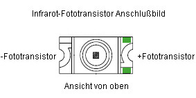
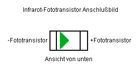
Fototransistoren empfangen das Licht und erzeugen damit einen Stromfluss.
IR-LED senden das infrarote Licht aus.
Kategorie:Bauteile
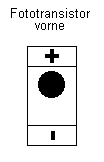
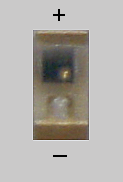
Fototransistoren
IR-Empfänger
Der IR-Empfänger bei DC01 und DC02 einzeln, ist bei DC04-SI, DC05-SI und DC06-I auf der Platine.
Die Fototransistoren von vorn übertragen die Signale, die vom Empfänger verstärkt werden.
Das darausentstehende Signal wird dem Prozessor zugeführt.
IR-Tester
Der einzelne Empfänger kann als IR-Tester benutzt werden.
File:IR-Tester.jpg
Hiermit kann man die Reichweite von den IR-Sendern prüfen und die Rückstrahler an den Autos.
Üblicherweise reicht das Signale kaum über 30 cm.
RC-Empfänger TSOP7000
TSOP = Remote Control Empfänger
File:TSOP.jpg
Zur Bedienung der Fahrzeug mit mehr Reichweite.
Der Empfänger reagiert auf den DC-Car-Booster und den PC-Empfänger.
Nur Anwendbar mit DC04, DC05, DC06.
Für DC01 und DC02 gibt es ein Austauschangebot.
Weitere Hinweise: TSOP7000
Veranstaltungen
Bezugsquellen
Links zu Car-Systemen
- MoBa-Claus (DC-Car-System und Modellbahn-Forum)
- Modellautobahnen.de (Informationen unter Technik)
- Miniatur-Wunderland (mit Modellbahn-Forum)
- Modellbau-Wiki vom Miniatur Wunderland Hamburg
Kategorie:Grundlagen (Car-System) Kategorie:Car-System Kategorie:DC-Car System Kategorie:Funktionsbaustein Kategorie:Handsender Kategorie:Reedschalter Kategorie:Vertrieb Kategorie:Hersteller
Kategorie:Grundlagen_GB (Car-System) Kategorie:Car-System_GB Kategorie:DC-Car System_GB Kategorie:Funktionsbaustein_GB Kategorie:Handsender_GB Kategorie:Reedschalter_GB Kategorie:Vertrieb_GB Kategorie:Hersteller_GB


