Instruction of Trafficlightdecoder
Contents
Trafficlightdecoder 2014
They should be trained to make fine soldering on circuit boards and components. You need a small soldering iron and thin tin solder. We recommend Sn60PbCu2 0.5mm diameter.
Work in no case with soldering grease !!! This harms the masterboard and the components.
You should also be dealing with ICs used and know how to look the individual components and what they mean. Since the board has no silkscreen, first look at the pictures carefully before proceeding.
| Widerstand | Modellbahnwerk | Mader-Magnet-Truck | other | |
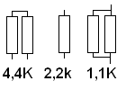
| 4,4 kohm | 1 Trafficlight | 0 Trafficlight | 0 Trafficlight | 2 Resistenz 2,2k in Reihe |
| 2,2 kohm | 1 Bogenampel | 1 Trafficlight | 0 Trafficlight | 1 Resistenz |
| 1,1 kohm | 2 arc lights | 1 arc lights | 1 Ampel | 2 Resistenz 2,2k parallel |
| 220 ohm | 5 arc lights | 2 arc lights | 1 Ampel | other Resistenz |
Partlist
Check out the master board 'and the' processor 'Ampel' 'in' SD Model Service in
and the other components by clicking on bei Reichelt.de
| Piece | Part | Instruction | Place |
| 1 | MasterBoard | Masterboard | Platine |
| 1 | Prozessor Ampel | Prozessor Ampel | IC1 |
| 1 | 1/4W 1,5K | Kohleschichtwiderstand 1/4W, 5%, 1,5 KOhm | R1 |
| 32 | 1/4W 2,2K | Kohleschichtwiderstand 1/4W, 5%, 2,2 KOhm | R4-R20 |
| 1 | 1/4W 270 | Kohleschichtwiderstand 1/4W, 5%, 270 Ohm | R2 |
| 1 | 1/4W 680 | Kohleschichtwiderstand 1/4W, 5%, 680 Ohm | R3 |
| 1 | 1N 4001 | Gleichrichterdiode, DO41, 50V, 1A | D3 |
| 2 | 1N 4148 | Planar Epitaxial Schaltdiode, DO35, 100V, 0,15A | D1,D2 |
| 1 | 6N 139 | OPTOKOPPLER | IC6 |
| 2 | AKL 101-02 | Anschlussklemme 2-polig, RM 5,08 | X4, X6 |
| 1 | AX 1.000/40 | Elko, axial, 1.000µF/40Volt | C2 |
| 1 | D-SUB BU 09EU | D-SUB-Buchse, 9-polig, gewinkelt, RM 9,4 | X3 |
| 1 | GS 16P | IC-Sockel, 16-polig, superflach, gedreht, vergold. | IC4 |
| 1 | GS 20P | IC-Sockel, 20-polig, superflach, gedreht, vergold. | IC2 |
| 1 | GS 28P-S | IC-Sockel, 28-polig, superflach, gedreht, schmal | für IC1 |
| 1 | GS 8P | IC-Sockel, 8-polig, superflach, gedreht, vergold. | für IC6 |
| 1 | LED 3MM RT | LED, 3mm, rot | LED |
| 1 | MAX 232 CPE | RS232-Driver, DIL-16 | für IC4 |
| 1 | PFRA 110 | Rückstellende Sicherungen, max. 40A-30V, 6,6s | F1 |
| 4 | AKL 059-05 | Anschlussklemme 5-polig, RM 3,5 | X7-X10 |
| 6 | TANTAL 1,0/35 | Tantal-Kondensator, Rm 2,5, 1,0µF/35V | C1, C3-C5 ,C7-C8 |
| 1 | TANTAL 4,7/10 | Tantal-Kondensator, Rm 2,5, 4,7µF/10V | C6 |
| 1 | TASTER 9302 | Kurzhubtaster 6x6mm, Höhe: 5,0mm, 12V, vertikal | Taster |
| 1 | V 4330K | Rippen-Kühlkörper, 35x29x12mm, 12K/W | Kühlkörper |
| 2 | µA 78S05 | Spannungsregler 2A positiv, TO-220 | IC3, IC7 |
building
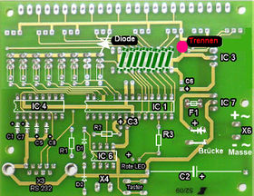
Thus, the board assembled (boards view from above = component side):
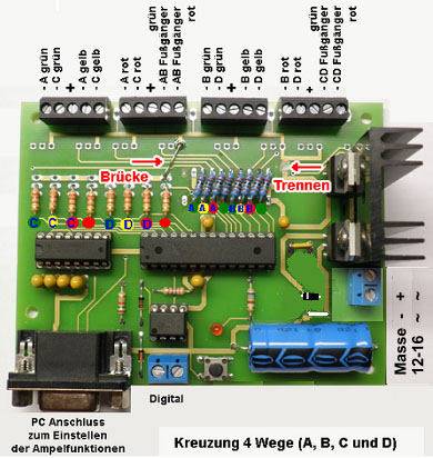
Begin with the modifications to the master board:
Carry out the separation using a sharp knife or a cutter.
Then use the bridge.
To adapt 'individual' lights resistors to change.
Plug the 28-pin socket for IC1 (28polig) into the corresponding holes.
Turn the board and solder to the base firmly.
Repeat the procedure with the bases for IC4 (16-pin) and IC6 (8-pin).
All bases have the notch on the left (see Figure 1)
Insert the two diodes D1 and D2 and solder. Attention! Note the correct position. Insert
Resistors R1 (1.5K) and R2 (270). (see Figure 2)
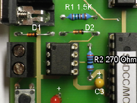 Figure 2
 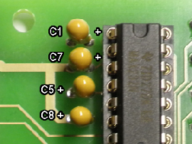 Figure 3
The capacitors (yellow, 1uF) C1, C3, C4, C5, C7 and C8 used.
(See the example for C1 in Figure 3).
Fit the condenser (yellow, 4.7uF or 1uF) C6.
Attention, all capacitors pay attention to the correct polarity (see figure 1).
Figure 4 shows the two capacitor types.
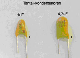 Figure 4
 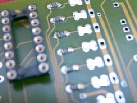 Figure 5
The resistors R4 - R19 (2K to 2.7K), according to Figure 1 are running.
If the lighting is too dark, the resistors 1 Kohm can be changed.
For SMD components the eye overlying must be bridged. Pictures 5.
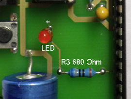 Figure 7
 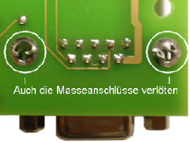 Figure 8
The solder button. Insert the resistor R3 (680 ohms) and solder.
The red LED so used, that it has some distance to the board. The long leg of the LED is the positive pole. See Figure 7.
Now even the 2-pin cable connections X4 and X6 Insert and solder.
Insert the 9-pin Sub-D connector X3 and solder. Also do not forget the two ground connections (Figure 8).
Solder the capacitor C2. Just note the polarity at this again.
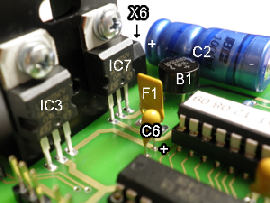 Bild 9
The diode 1N4007 and bridge (instead of the rectifier) used to position B1 and solder. Attention! Note the correct position.
The fuse F1 solder. The two voltage regulators are loosely bolted to the heat sink. Now insert the two voltage regulators IC3 and IC7 (78S05) to their position on the board.
The heatsink is located on the 2-pin terminal block X6 on (see also Figure 9).
In this position, the voltage regulator to be soldered and tightened the screws afterwards. For fixing, you can screw the heatsink on the board with the board from the bottom, or secure it with glue.
This heatsink is sufficiently dimensioned for all 16 Traffic Lights.
If everything is soldered clean and no soldering is forgotten, you can now connect the AC voltage (12-16 volts) or DC voltage (9-12 volts) from your transformer to the socket X6 for the first time.
Use a voltmeter to check that bears a direct voltage of 5 volts between the negative terminal of C2 + and the increase of C6. Even with the 5-pole screw terminals of the center pole should have 5 volts. If so, then everything is ok.
Voltage off !!
Now, the ICs are used. All shown with the notch or the point as in picture 1.
IC1 = ATmega168-20PI Ampel234 IC4 = MAX232 IC6 = 6N139
Switch voltage back on. If any IC gets hot, then turn off power immediately and check the position of the ICs, short circuits on board, etc.. You can now connect the traffic lights.
We wish you every success in the assembly
Information
More Informationen and Updates:
dc-car.de
Modelleisenbahn-claus.de
www.modellautobahnen.de/download/Ampeldecoder/Bauanleitung Ampeldecoder2014.pdf
Traffic lights, with common plus pole:
See Traficlight
Application
application see Trafficlightdecoder
